


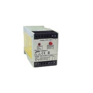
Leckstar 255 relay for JOLA leak detectors

Po naročilu. Pošljite povpraševanje.
Delivery time: okvirno 2 tedna
- supply voltage: 230 V AC; other voltages on request
- Power supply: approx. 3 VA
- switching voltage: max. AC 250 V
- short-circuit protection: short-circuit current limit ≤ 30 mA

Description
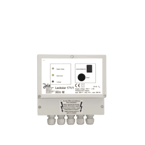
The Leckstar 255 relay for JOLA leak detectors is designed for limit level signalling. They shall be installed in a control cabinet or other suitable protective enclosure. The switches are suitable for use in clean environments.
- with cable disconnection control function
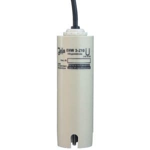
- for connection of 5 conductive electrodes with Z10 cable break monitoring unit
- with a touch button to acknowledge the alarm
- with two potential-free switching contacts at the output and
- with 5 status signal outputs, DC 20 V, for building monitoring system
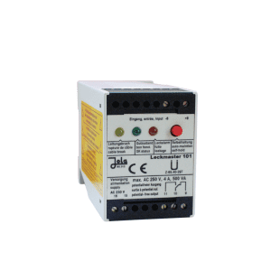
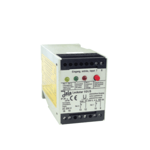
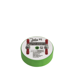
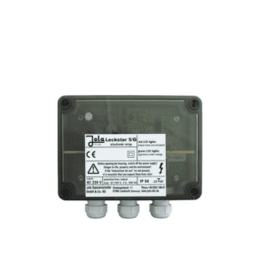
Relay electrodes in surface-mount housing, with transparent cover, 5 x 4 LEDs for operation status and 1 LED for confirmation status, inside the housing
-
5 signal lines with common system earths
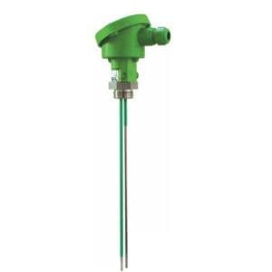
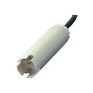
The Leckstar 255 electronic relay has inputs for connecting 5 signal lines. The signal line consists of one or more conductive electrodes.
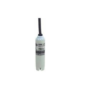
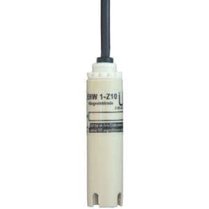
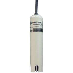
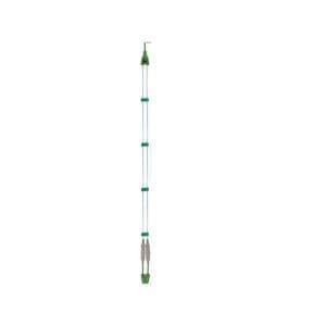
If electrodes designed for this purpose are used, several electrodes can be connected one after the other to allow control of cable breaks at any point along the line. At the end of each signal line is an electrode with an integrated Z10 cable break control unit. No other electrode in the signal line shall be equipped with a cable break monitoring unit.
In principle, the conductive electrodes commonly used consist of at least 1 pair of electrode leads (at least 1 control electrode and 1 earth electrode).
The electronic circuits are supplied with a safety extra-low voltage generated by the Leckstar 255, which is reliably galvanically isolated from the mains circuit and the potential-free switching contacts of the two output relays.
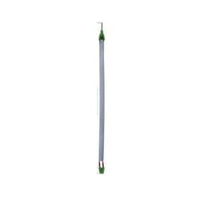
All 5 signal lines share a common system earth, which means there is no galvanic isolation of the signal lines. This factor should always be taken into account for long signal lines of cable, strip, double or mat electrodes extending into different parts of the building. If the electrodes are positioned in such a way that the electrode can assume the ground potential, there is a risk of ground loops. It may be necessary to perform local potential equalisation to avoid potential equalisation currents across the signal lines.
-
Activating individual signal lines
If you are not using all 5 signal lines, you can activate (dip switch in active position) or deactivate (dip switch in inactive position) signal lines 2 to 5 individually via the 4 dip switches. Channel 1 is always activated. Activation/deactivation can only be performed in the no-flow state.
-
Type of indication
Each signal line is assigned a group of 4 LEDs of different colours.
-
Power circuit
Two potential-free switching contacts are available at the output, one of which reacts according to the operating current principle and the other according to the quiescent current principle. In addition, there is a DC status output signal of 20 V DC based on the quiescent current principle for each signal line of the building control system. The potential-free switching contact, based on the operating current principle, can be identified by a touch key operating through the unit’s housing cover.
Before use, we recommend viewing the attached pdf documents under the Documentation tab.
Leckstar 255 features
- supply voltage: 230 V AC; other voltages on request
- Power supply: approx. 3 VA
- Electrode circuit: 5 terminals under safety extra-low voltage, for 5 signal lines without galvanic isolation from each other, with common earth connection
- no-load voltage: 18 Veff 10 Hz (safety low voltage SELV)
- short-circuit current: max. 0.5 mAeff
- response sensitivity: approx. 30 kW or approximately 33 µS (electrical conductivity)
- first power circuit: 1 single-pole potential-free switching contact, based on the operating current principle, for group alarm in case of leakage or cable breakage, can be confirmed by touch key
- second power circuit: 1 single-pole potential-free switching contact, based on the quiescent current principle, for group alarm in case of leakage or cable breakage
- switching voltage: max. AC 250 V
- switching current: max. AC 4 A
- switching power: max. 500 VA
- Third power circuit: 5 terminals under safety extra-low voltage for a 20 V DC binary switched-state output signal of each of the 5 signal lines, without galvanic isolation from each other, with a common earth connection
- No-load voltage: 20 V DC (sufficient for 24 V inputs, as a high signal usually requires at least 15 V)
- short-circuit protection: short-circuit current limit ≤ 30 mA
For more information, please see the attached pdf documents under the Documentation tab.
Welcome to the article ”Conductive Measurement of Liquids”
Povpraševanje
You may also like…


For your victories, with our solutions. Call us:
Contact us.
Call us:
+386 (0)2 62 96 720
Email us:
[email protected]