


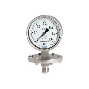
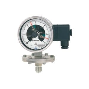
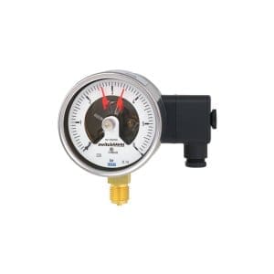
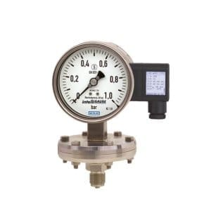
PGS43.160 diaphragm pressure gauge with switchable contacts WIKA

Po naročilu. Pošljite povpraševanje.
- wide choice of special materials
- up to 4 switch contacts per instrument
- instruments with contacts for PLC applications
- high reliability and long lifetime
- instruments with inductive contacts for use in hazardous areas
- also available with liquid filling for high dynamic pressure loads or vibrations

Description
The PGS43.160 diaphragm manometer with switchable contacts from WIKA is used for differential pressure monitoring, the instrument allows switching and display.
Wherever process pressure needs to be specified locally and circuits need to be made or broken at the same time, the model PGS43.160 switchGAUGE can be used.
Switch contacts (electrical alarm contacts) make or break the electrical control circuit depending on the position of the instrument pointer. The switch contacts are adjustable over the full range of the dial (see DIN 16085) and are located mainly under the dial, but also partly on the top of the dial. The instrument pointer (actual value indicator) moves freely over the full scale range, independent of the setting.
You can adjust the set cursor using the removable adjustment key in the window.
You can also set multiple contacts to a single set point. The contact is triggered when the actual value pointer moves above or below the desired set point.
The pressure gauge is manufactured in accordance with DIN 16085 and meets all the requirements of the relevant standards (EN 837-3) and regulations for the on-site indication of the working pressure of pressure vessels.
Magnetic contacts, reed switches, inductive contacts and electronic contacts are available as switch contacts. Inductive contacts can be used in hazardous areas. Electronic contacts and reed switches can be used to trigger programmable logic controllers (PLCs).
Features of PGS43.160
- Nominal size in mm: 100
-
Accuracy class:
- 1.6
- Option:
- 1.0
-
Scale range:
- 0 … 25 mbar to 0 … 250 mbar (flange Ø 160 mm)
- 0 … 400 mbar to 0 … 25 bar (flange Ø 100 mm)
- other units available (e.g. psi, kpa)
- or any other equivalent pressure and vacuum ranges
-
Scale:
- Single scale
- Option:
- Double Scale
-
Pressure limit:
- Constant value of the overall scale
- Niha 0.9 x total scale value
-
Safety against overloading:
- 5 x full scale, but not more than 40 bar
- Options:
- Overload protection up to 10 x full scale, max. 40 bar
- Suction safety up to -1 bar
-
Process connection to the lower measuring flange:
- G ½ B
- ½ NPT
- M20 x 1,5
- Open connection flange DN 25 PN 40 to EN 1092-1, Form B
- Open connection flange DN 50 PN 40 according to EN 1092-1, Form B
- Open connection flange 1″ Class 150, RF to ASME B16.5
- 2″ Class 150, RF open connection flange per ASME B16.5
- and other threaded connections and open flanges according to EN/ASME from DN 15 to DN 80 (see technical data sheet)
-
Allowable temperature:
- Medium +100 °C maximum
- Option:
- +200 °C maximum
- Environment -20 °C … + 60 °C
- Temperature effect When the temperature of the measuring system deviates from the reference temperature (+20 °C): max. ± 0.8 % / 10 K full scale
-
Housing version S1 to EN 837:
- With blowing device in the housing
- Option:
- Safety version S3 according to EN 837: with solid barrier wall (Solidfront) and back exhaust
- Instruments with liquid filling with compensation valve up to vent housing
-
Charging the housing
- Without
- Option:
- With M50 silicone oil housing filler, ingress protection IP65
-
Wet materials
- Membrane element (pressure element):
- ≤ 0.25 bar: 316L stainless steel
- > 0.25 bar: NiCr alloy (Inconel)
- Option: coated with special materials such as PTFE, Hastelloy, Monel, nickel, tantalum, titanium, silver (instruments with accuracy class 2.5)
- Process connection to the lower measuring flange:
- 316L stainless steel
- Option: lined/coated with special materials such as PTFE, Hastelloy, Monel, nickel, tantalum, titanium, silver
- Pressure chamber sealing: FPM / FKM
- Membrane element (pressure element):
-
Non-moisturised materials:
- Housing with upper measuring flange, movement, bayonet ring
- Stainless steel
- Aluminium dial, white, black
- Instrument pointer Aluminium, black
- Setting indicator Aluminium, red
- Window Laminated safety glass
- Housing with upper measuring flange, movement, bayonet ring
-
Ingress protection according to IEC/EN 60529:
- IP54
- Option:
- IP65
-
Electrical connection
- Cable socket PA 6, black
- To insulation group VDE 0110 C/250 V
- Cable gland M20 x 1.5
- Relieving strains
- 6 screw terminals + PE for conductor cross section 2.5 mm²
- For dimensions, see technical data sheet
- others on request
For more features of the PGS43.160 and additional options, we recommend viewing the attached .pdf documents under the Documentation section.
Areas of use, applications
- plant control and switching of electrical circuits
- for gaseous and liquid, aggressive and highly viscous or contaminated media, also in aggressive environments
- control and regulation of industrial processes at measuring points with increased overpressure and ranges from 0… 25 mbar
- Process industries: chemical, petrochemical, power plants, mining, offshore and onshore, environmental technology, mechanical engineering and general plant construction
ELPRO designation: MAN-PGS43.160
Povpraševanje
You may also like…

For your victories, with our solutions. Call us:
Contact us.
Call us:
+386 (0)2 62 96 720
Email us:
[email protected]