


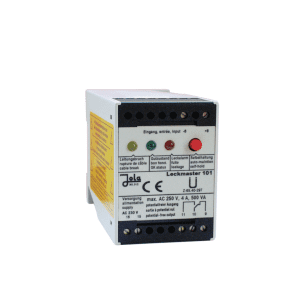
Leckmaster 101/Ex relay for JOLA capacitive detectors

Po naročilu. Pošljite povpraševanje.
Delivery time: okvirno 2 tedna
- supply voltage: 230 V AC; on request: 240, 115, 24 V AC or 24, 12 V DC
- Power supply: approx. 3 VA
- switching indicator: via 3 LED lights
- switching voltage: max. AC 250 V
- temperature range: – 20 °C to + 60 °C
- EC type-examination certificate: INERIS 03ATEX0159

Description
The Leckmaster 101/Ex relay for JOLA capacitive detectors is designed for limit level signalling. They shall be installed in a control cabinet or other suitable protective enclosure. The switches are suitable for use in clean environments.
Capacitive Ex relay for U-rail mounting or surface mounting, with connection terminals on top and 3 built-in LEDs to indicate operating conditions.
The unit is designed to be installed or mounted in a suitable protective enclosure outside potentially explosive atmospheres and can therefore only be installed/mounted in these locations. It is only suitable for use in clean environments.
The Leckmaster 101 Capacitive Ex Relay / Ex I (M1) / II (1) GD [Ex ia Ma] I / [Ex ia Ga] IIC / [Ex ia Da] IIIC is designed to transfer control commands from an intrinsically safe control current circuit to a non-intrinsically safe active current circuit. It must be installed outside potentially explosive areas in accordance with the relevant standards and regulations.
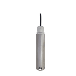
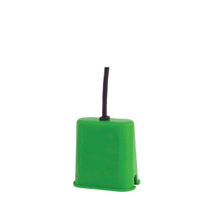
An Ex-approved capacitive sensor such as our capacitive COW/Ex-1G, COW/Ex0G, OWE/Ex-1G, OWE/Ex-0G or OWE 2/C/NL/Ex-1G can be used through the device. Mandatory Ex junction box OAK/LMT/2x1MW II 2 G Ex ia IIC T6 Gb, in a safe control circuit. The different application options and specific conditions for safe use are described in the relevant installation, operation and maintenance instructions (sent on request).
Before use, we recommend viewing the attached pdf documents under the Documentation tab.
Features of the Leckmaster 101/Ex
- supply voltage: 230 V AC; on request: 240, 115, 24 V AC or 24, 12 V DC
- Power supply: approx. 3 VA
- electrode circuit. 2 terminals (under safety extra-low voltage SELV) operating on 1 output relay with switching self-test
- No-load voltage: 8.4 V DC (under safety extra-low voltage SELV)
- short-circuit current: < 10 mA
- response hysteresis: 1.5 mA 1.8 mA
- cable break monitoring: I < 0.15 mA
- control circuit: 1 single-pole potential-free switching contact based on the quiescent current principle
- switching indicator: via 3 LED lights
- switching voltage: max. AC 250 V
- switching current: max. AC 4 A
- switching power: max. 500 VA
- housing: insulating material, 75 x 55 x 110 mm
- connection: terminals on the housing
- protection class: IP20
- Installation: U-bolt fixing according to DIN 46 277 and DIN EN 50 022 or fixing via 2 drill holes
- orientation of installation: any
- temperature range: – 20 °C to + 60 °C
- EC type-examination certificate: INERIS 03ATEX0159
For more information, please see the attached pdf documents under the Documentation tab.
Povpraševanje
You may also like…
For your victories, with our solutions. Call us:
Contact us.
Call us:
+386 (0)2 62 96 720
Email us:
[email protected]