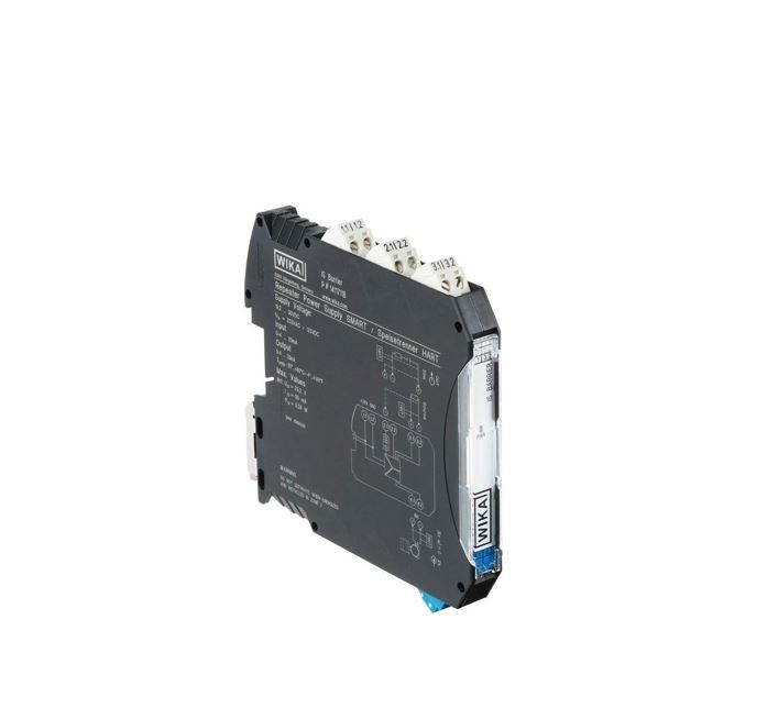
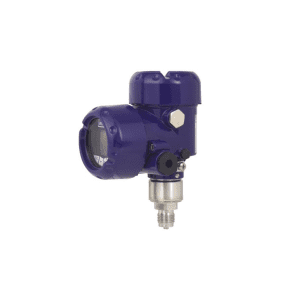
IS barrier, Wika explosion-proof proprietary device
Po naročilu. Pošljite povpraševanje.
Delivery time: okvirno 2 tedna
- Two-way download signals HART®
- suitable for SIL 2 according to IEC 61508/IEC 61511
- 0/4 ... 20 mAinput, power and non-power
- operating temperature range: -20 °C … +60 °C
- permissible humidity: 10 … 95 % (non-condensing)
Description
IS barrier, Wika explosion-proof proprietary device
is a certified proprietary device in the anti-explosion version. Itis designed foruse in combination with intrinsically safe Ex devices with ATEX 4 ... 20 mA certification.
Z udifferent terminals can be used to connect both 2-wire and 4-wire inverters. The analogue measured value is transferred to the zone, which is not hazardous and is galvanically separated from the hazardous area. On the output side, the repeater power supply can operate as a power supply or unpowered. The test sockets in the COMBICON connectors allow direct connection of HART® communicators.
The repeater power supply has been tested to work with the following WIKA products:
Main features
- Two-way download signals HART®
- suitable for SIL 2 according to IEC 61508/IEC 61511
- 0/4 ... 20 mAinput, power and non-power
- operating temperature range: -20 °C … +60 °C
- permissible humidity: 10 … 95 % (non-condensing)
Technical specifications
Input:
- Input: active current input, self-powered
- input signal, current: 4 … 20 mA
- current limit: 25 mA
- power supply to the converters:
- > DC 16 V (for 20 mA)
- > DC 15.3 V (for 22.5 mA)
- Under- and overload signal range: 0 … 24 mA (extended transmission range for diagnostics)
Exit
- Output:
- current output (active and passive)
- 1 : 1 transmission per input signal
- signal range under and overload:
- 0 … 24 mA (extended transmission range for diagnostics)
- the burden:
- < 1.000 Ω at 20 mA
- < 825 Ω at 24 mA
- Output waveform: < 20 mVeff
- behaviour in the event of an error in accordance with NE43:
- 0 mA (cable break at input)
- ≥ 22.5 mA (cable short circuit at input)
Galvanic isolation
- input/output/supply voltage
- insulation voltage: 300 Veff
- Overvoltage category II
- Pollution level 2
- safe insulation according to EN 61010-1: 50 Hz, 1 min.
- test voltage: 2.5 kV
- input/output
- Peak voltage according to EN 60079-11: 375 V
- input/power supply voltage
- Peak voltage according to EN 60079-11: 375 V
Power supply
- power supply
- rated voltage: DC 24 V
- Voltage range: DC 19.2 … 30 V
- max. current care
- < 76 mA (DC 24 V / 20 mA / 1.000 Ω)
- < 55 mA (DC 24 V / 20 mA / 250 Ω)
- dissipation loss
- out, active:
- < 1.1 W (DC 24 V / 20 mA / 1.000 Ω)
- < 0.95 W (DC 24 V / 20 mA / 250 Ω)
- output power, passive: < 1.2 W (DC 24 V / 20 mA / 0 Ω)
- out, active:
- power consumption (active output)
- < 1.8 W (20 mA / 1000 Ω)
- < 1.3 W (20 mA / 250 Ω)
Precision specifications
- transmission error
- < 0.05 % of the final value (typ.)
- < 0.10% of the final value (max.)
- temperature coefficient
- < 0.004 %/K (tip.)
- < 0.01 %/K (max.)
- step response (10 … 90%)
- < 200 μs (in steps of 4 mA … 20 mA, 600 Ω load)
- < 600 μs (0 mA … 20 mA step, 600 Ω load)
Operating conditions
- ingress protection: IP20
- Overvoltage category: II
- flammability class according to UL 94: V0
- Pollution level: 2
- permissible ambient temperatures
- operation: -20 … +60 °C
- Storage: -40 … +80 °C
- permissible humidity: 10 … 95 % (non-condensing)
- mounting position: as required
Materials
- Cover: PA 66-FR, anthracite grey (RAL 7016)
Electrical connections
- test socket diameter: 2 mm
- wire cross-section:
- Rigid wire 0.2 … 2.5 mm²
- flexible wire 0.2 … 2.5 mm²
- AWG 24 … 14
- torque: 0.5 … 0.6 Nm
- reverse polarity protection: yes
HART® communication
- supported protocols: HART®
- Signal bandwidth: meets HART® specification
Safety information according to ATEX
- operating mode: power isolated amplifier
- max. output voltage U0: DC 25.2 V
- max. output current I0: 93 mA
- max. Output power P0: 587 mW
- Group
- (Max. external inductance L0 / Max. external capacitance C0 )
- IIB: 4 mH / 820 nF
- IIC: 2 mH / 107 nF
- Maximum Um voltage: AC 253 V / DC 125 V
Types of ignition protection
- ATEX
- II (1) G [Ex ia Ga] IIC/IIB
- II (1) D [Ex ia Da] IIC
- II 3 (1) G Ex nA [ia Ga] IIC/IIB T4 Gc
- I (M1) [Ex ia Ma] I
- IECEx
- [Ex ia Ga] IIC/IIB
- [Ex ia Da] IIIC
- Ex nA [ia Ga] IIC/IIB T4 Gc
- [Ex ia Ma] I
- cULus
- UL 61010 listed
- Class I, Div. 2, Groups A, B, C, D T4
- Class I, Div. 2, Groups IIC, IIB, IIA T4
- associated apparatus for use in Class I, Division 1, Groups A,B,C,D
- associated devices for use in Class II, Div.1 groups E, F, D
- associated apparatus for use in Class III, Division 1
- associated installations for use in Class I, Zone 0,1,2, Groups IIC,IIB,IIA
Dimensions in mm
- W x H x D: 12.5 x 99 x 114.5 mm(without terminals)
Scope, applications IS Barrier
- chemical, petrochemical
- oil, natural gas
- construction machinery
Other designations: IS_barrier, IS-barrier, IS barrier_Ex
Povpraševanje
You may also like…
For your victories, with our solutions. Call us:
Contact us.
Call us:
+386 (0)2 62 96 720
Email us:
[email protected]

